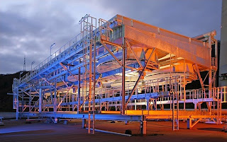
Untitled-3
Showing posts with label Air Cooled Heat Exchanger. Show all posts

Thursday, 1 October 2015

Air Cooled Heat Exchanger and Its Benefits

This air cooled heat exchanger is utilized in refineries, gas, petrochemical, and chemical plants. They are customized for customers' requirements in complex installations, critical applications and tough conditions. 

The air cooled tube bundle covers the full range of metallurgies from low and carbon steel, duplex and super-duplex stainless steel, stainless steel, titanium and nickel alloys. The bundle also includes plugs, covers or a high pressure manifold header boxes design, as well as the complete range of extruded, L-footed or embedded aluminum tubes fins.


Heat exchanger is widely popular as industrial equipment which is designed for transferring heat from one medium to another. It is widely used in factories and industries for transferring heat energy. As this equipment is especially designed for transferring energy therefore it is separated by a solid wall which prevents the chances of mixing each other. There are two side walls, first is associated with hot fluid whereas the other is related to cool fluid which keeps the flow through channels. Both these channels enable the equipment to perform efficiently and conveniently. It works as per the industry needs. Fins and corrugations are another parts designed in this equipment that transfers the heat in best possible manner. The heat exchanger manufacturers are efficient in designing the equipment along with diverse kinds of parts including Air dryer, Air receiver, Pressure vessel, etc.
Types of Heat exchanger
Shell And Tube
Adiabatic Wheel
Plate Fin
Pillow Plate
Dynamic Scraped
Uses:It is widely used in industries such as chemical plants, refrigeration, space heating, power plants, natural gas processing, petroleum refineries, sewage treatment, air conditioning, natural gas processing and many more. Each of these industries uses this equipment as per the requirement. It's equipment helps the industries in their manufacturing and production process. The experts and professionals of the organization get training to operate this equipment as any kind of small negligence can create trouble for entire factory. Thus, several precautions are taken to operate it or use it.
BenefitsAdaptability: The modern and tech centric heat exchangers are versatile in nature and perform several tasks. It are in compact size and quite portable as well. The flexible features of the heat exchanger are made for different industries with unique design. Modern Heat Transfer System: Being the advance system, they can cover larger areas as well. The machine is enough capable to produce a high turbulent flow and excellent distribution of temperature. Temperature Management: The device is efficient in managing high temperature for perfect flow. 
The efficient equipment is capable for high temperature and pressure ratings. Maintenance: As the modern equipment doesn't corrode easily therefore it is easy to maintain. Secondly, the parts of this equipment are easy to replace. The non-functional parts can be removed easily and it is a DIY job. Material: The heat exchangers are available in different material, design and shape. The common materials used for this equipment are titanium, stainless steel, nickel, palladium and tantalum. Price: New versions and modern designs are available with heat exchanger manufacturers. Due to the high competition and demand these are available at cost effective prices. 
 
Professionals can get the best and efficient as per the demand and requirement of the industry. The experts are available in market to provide the installation and demo service as well. Thus, professional can easily get the cost effective and efficient heat exchanger without any doubt or worry, as experts are ready to cater the assistance at any point of need.

Wednesday, 30 September 2015

Air Cooled Heat Exchangers

Air cooled heat exchangers are only one of various kinds of heat exchanger. Heat exchangers are gadgets which are specially designed for aiding the transfer of heat from one fluid towards the other. For us to better understand, typical samples of devices that use heat exchangers include the air conditioners, refrigerators as well as space heaters.

But let us not dwell a lot of over the general heat exchanger rather let's now take a look at air cooled heat exchangers or ACHEs for short. It rejects heat from a hot fluid directly to fan-blowing ambient air. ACHEs are commonly utilized each time a procedure or set up creates heat that has to be removed and regrettably lacks local use. Your car's radiator is actually an example of ACHE device. The engine must be cooled to prevent overheating due to friction and combustion functions by the engine. The excess heat is taken away by the water or glycol coolant mix. Majority of the heat should be taken away, and the best way is as simple as supplying ambient air.

There are more functions for air cooled heat exchangers, including the upstream production, refineries and petrochemical facilities. It can also be used on conditions with high temperature, high pressure, corrosive fluids and environments. Moreover, air coolers is usually equipped and used in gas and oil refineries; compressor stations for oil pipelines; subsurface gas storage facilities; plants producing polychlorvinyl, polyethylene, glass fiber, biplastic; caustic soda plants; by-product coke plants and ammonia transportation and handling plants.

Besides learning the actual functions of ACHEs, we should have a view upon how it operates inside and its elements. Usually, air coolers for process application are composed of a finned-tube bundle with rectangular container headers on both ends of the tubes. Headers are boxers that dispense the fluid from the piping to the tubes. The other parts include one or more fans that give cooling air. The fans are generally powered by electric motors and are also accompanied by speed reduction devices. The fan drive assemblage is sustained by the metal mechanical drive support system. Generally, the air flows up-wards all the way through a horizontal tube bundle. The fans could be either forced or induced draft, dependant upon whether the air is pushed or pulled through the tube bundle. Forced draft unit enables a simple access for maintenance for the fans and the bundles. Furthermore, the fans stay in the cold ambient air. Whilst the induced draft unit provides a stable as well as strong thermal performance because of the protection of the finned surface against wind, rain, hail and snow by the plenum chamber. The induced draft also guarantees an improved air distribution, much less hot air recirculation, much less air-side fouling and lower noise levels at grade. Space in between the fans and the tube bundle is encircled by a plenum chamber, that directs the air. The full assembly is usually installed on legs or perhaps a pipe rack.

Understanding and knowing the inside and out of ACHEs is fairly difficult, especially for those who have no background in mechanical matters. And for this reason, let us once again move our attention on another subject matter, which is the "why" question. With regards to economy, air coolers are preferred due to the lower maintenance expenses. Some other benefits offered by air coolers are as follows: lack of the need for cooling water or other cooling media, no issue shall arise with regards to the thermal as well as chemical pollution of cooling fluids, and it quite fast to install by bolted assembly.

ACHEs are regarded as a "green" alternative because no chemical treatment methods are required to the water or fluid used by the assembly. And temperature is the only parameter that has to be considered whenever getting rid of the water used. Without a appropriate heat exchanger equipment, overheating will ruin your equipments and appliances, specially the parts subjected to heat. Out of all of the things that have been pointed out, if we are to consider the trend that the world is going, air cooled heat exchanger are the ideal choice for industrial plants and other plants if the environment is to be considered.

Monday, 11 May 2015

What Is a Chiller Plant Design and How Do They Work?

A chiller plant design consists of many pieces of HVAC equipment that are all interconnected by piping to form a chiller plant. This article will look at a water cooled chiller plant design.

The major parts of a water cooled chiller are the compressors, the evaporator heat exchanger (piping circuit #1) and the condenser heat exchanger (piping circuit #2). There are two separate piping circuits in a chiller plant design.

A chiller produces cold water that is typically circulated (pumped) to cooling coils that are inside air conditioning units. This is called the chilled water piping circuit, circuit #1.
The air conditioning unit fan takes air from a room and blows this air across the cooling coil to produce colder air and then circulates this colder air through a duct system to cool the room.

Once the cold water from the chiller cools the air, it becomes warmer, and it must be circulated back to the chiller so that it can become cooler again.

A chiller uses a refrigerant to cool the water, but once it cools the water the refrigerant becomes warmer and it rejects its heat to the cooling tower (or condenser water) piping circuit, circuit #2, so that the entire process can start over.

The basic design consists of a chiller or multiple chillers, chiller water pumps for the chilled water piping circuit, a cooling tower or towers and cooling tower pumps for the cooling tower water piping circuit.

In a water cooled chiller plant design, there is a cooling tower which is considered a heat rejection device and it takes the unwanted heat from the chiller, by circulating water through the chiller and then takes this warmer water and rejects this heat to the tower. The tower then takes the heat from the water and rejects this heat into the atmosphere. This is the second piping circuit and is called the condenser water circuit.

There are many different types of chillers that must be considered in a chiller plant design. The difference is the type of compressors and the difference in efficiencies in each type. There are scroll type compressors, reciprocating type, screw type, centrifugal type and there are chillers that do not use compressors such as steam absorption type chillers.

In a chiller plant design the chiller is selected based upon the amount of tons of cooling that it can produce. A ton of cooling is equal to 12,000btuh. So a 20 ton chiller has a 240,000btuh cooling capacity. The chiller cooling capacity must be equal to or greater than the cooling requirements of the building at peak load which occurs during the summer.
A chiller plant design is usually required for larger buildings with multiple floors because it is much easier to pump water around a building than it is to circulate air. The chiller plant is centrally located and chilled water is pumped to air conditioning units that are located closer to the areas that they have to cool.

Looking forward for Air Cooled Heat Exchanger ? Please visit here.

Sunday, 10 May 2015

Energy Efficiency in Air Cooled Chillers

An air cooled water chiller removes heat from water or other process fluid by use of a refrigeration system that then dissipates that same heat into the air. The energy efficiency is given by the chiller COP.

 The chiller operates by using the change of state of a refrigerant gas which when forced through an orifice at high pressure changes state from a liquid to a gas, absorbing heat through the chiller evaporator heat exchanger. This cold expanded gas then travels to the chiller refrigeration compressor where it is compressed into a hot, dense gas and pumped to the chiller condenser. The volume that the compressor can pump, the refrigeration gas used, and the operating conditions determine how much heat is removed.

At the air cooled chiller condenser the refrigerant is forced by the compressor through smaller copper tubes which have thin aluminum fins mechanically bonded to them. Ambient air is then forced through the condenser coil by the chiller fans. This causes the hot refrigerant gas to condense into a liquid, changing state, and releasing the heat that the gas collected at the chiller evaporator. The waste heat is then carried away into the ambient air by the fans. The liquid is then forced through the orifice and the process starts again.

The heart of the chiller is the refrigeration compressor. This is a pump that uses electrical energy to pump refrigerant around the system. Depending on the application like size or operating temperature, a different compressor pumping technology is used. Smaller chillers use refrigeration compressors like rotary compressors, scroll compressors, and reciprocating compressors. Larger chillers use refrigeration compressor like reciprocating compressors, screw compressors, absorption compressors, and centrifugal compressors.

Each type of refrigeration compressor can operate more or less efficiently in the air cooled water chiller depending on the water or glycol outlet temperature required, the ambient air temperature conditions and the chiller refrigerant used.

 The efficiency of the chiller compressor is given by the COP or Coefficient of Performance which is the ratio of kW of heat removed to kW electrical input required. The higher the chiller COP is, the better the energy efficiency. For example a COP of 3 means that for every 1 kW of electrical input, 3kW of heat is removed from the water. A chiller COP of 5 means that for every 1kW of electrical energy input, 5kW of heat energy is removed from the water.

 Typically chiller COP will vary as follows:
1. Holding the chiller condensing temperature constant: a lower chiller evaporating temperature will use more electrical power per kW heat removed and the chiller COP will be worse, while a higher chiller evaporating temperature will use less electrical power per kW of heat removed and the COP will be higher. 

2. Holding chiller evaporating temperature constant: a higher chiller condensing temperature will have a worse chiller COP that having a lower chiller condensing temperature.

 A customer's process cooling requirement will determine the operating temperature for the air cooled water chiller. For example an air conditioning chiller will require water typically at 7 deg C outlet from the chiller evaporator and 12 deg C return. This would require a chiller refrigerant like R407C which is fine for ambient air environments of up to 45 deg C.

 Where a higher chiller water outlet temperature is required a chiller refrigerant gas like R134a would be acceptable and this has the added benefit of allowing the chiller to operate in much higher ambient conditions - for example - chillers in the Middle East and chillers in Australia - remote locations like mine sites - are often located where the ambient air can be 50 deg C or above.

Click here for Air Cooled Heat Exchanger.

Friday, 8 May 2015

Air Heat Exchangers - The Good, the Bad, and the Ugly

Air exchangers often are used to perform many functions such as reducing air contamination, heating or cooling air entering the building, and humidifying or dehumidifying air before it enters the building. Air to air heat exchangers or heat recovery ventilators, are used to provide a balanced flow of air into and out of a building. Ultimately an air exchangers main function is to switch the stale inside air with fresh outside air while exchanging the heat or cool in the process.

An air-to-air exchanger is used to recover heating or cooling and to improve the air quality of the building that it serves. Typically an exchanger has two fans, one blowing air into the house and one blowing air out of the house. In the winter time the one fan brings the outdoor cool air through the core warming it with the warm stale air you are exhausting. In the summer time the warm air from the outside will be cooled as it enters through the core to save on your cooling.

The amount of air that these exchangers bring into a home may vary depending on how the system has been installed. The codes in many places require a minimum amount of air to be exchanged. Check with your codes official to see what the requirements are for you.
There is some controversy about the savings of exchangers. Not only does it require electricity to run the air exchanger, but the air the exchanger brings into your house must be brought up to temperature. This may require that more electric is used to cool your building or that more fuel is also required for heating.

Many air exchangers are controlled simply by on and off switches, but in some applications where the removal of humidity is required, then a humidistat can be used to turn the machine on and off to achieve the humidity level that you want. In cases where there may be a lot of humidity the air exchanger may not be enough to solve the problem. Other devices may be needed to lower the humidity to the level that you want.

All air heat exchangers will require regular maintenance. The problem is that this is almost never performed by homeowners, and unless they know about the exchanger it is often overlooked by contractors during service calls. The real problem is that clogged, air-to-air exchangers can make the indoor air significantly worse than it would be without the system installed at all. If you have a home that already has a heat air exchanger, make sure that you keep it very well maintained or disconnect it.

Exchangers can be a very good thing for many buildings. Especially those that are very large and typically have a lot of occupants with little natural air exchange from doors or windows being opened. However they are also a health hazard if they are not serviced regularly. Make sure that if you live or work in a building that has air exchangers that you see to it that they are serviced properly.

Please visit here for more info about Air cooled heat exchanger.


Tuesday, 31 March 2015

Air Cooled Heat Exchangers for All Equipment

An air cooled heat exchanger is amongst the must-haves for all equipment. It is a commonly known fact that when a machine works hard for a prolonged period of time, it can easily heat up and damage itself. In fact, in many cases, when a machine overheats, the consequences can be direr. Factories have caught fires and burned down to the ground simply because the equipment running inside overheated and caused a fire to break out. Thus, it is very important for the equipment to have cooling systems installed inside them to keep them at low temperatures as they function. An air cooled heat exchanger is able to do exactly that. It manages to use the heat of the system to work on and it slowly turns the hot air down to cooler temperatures.

Cover plate Configuration

Some air cooled heat exchangers have a cover plate configuration system and these types are generally used in machines that are installed in refineries. They are supposed to work with machine oils and heavy hydrocarbons, cooling them down as the oils and hydrocarbons power the machines that are supposed to pump out the oil. This type of an air cooled heat exchanger is very easy to maintain. In fact, it has been designed for easy maintenance so that the costs are kept low. The cover is flanged is easily removable and allows cleaners to access the components inside. While this exchanger is quite good at the machines it is built for, it is not recommended for sensitive service applications since it limits the design pressure a lot.


Plug box Configuration

This type of an air cooled heat exchanger is full of possibilities, is highly flexible and can be used in a number of different settings. Since it can work just as well with all kinds of hydrocarbons and gases and can be fitted anywhere in the entire factory (to gel in with all kinds of processes) the demands for this are very high as well. It can be fitted in big and small plants to operate equally well in any condition. The distributor, or the header, of this kind of exchanger is a welded box which is located near the finned tube. It has small holes in it so that one can clean it out without screwing it open and removing the components. It has very low costs but high versatility so is able to meet all sorts of industry demands.

Pipe and Bend Configuration

This kind of air cooled heat exchanger is mostly used when one only has to work with fluids and not gases or hydrocarbons of any kinds. It can come in many different sizes so it can be installed in huge factories or small ones equally well. The header is simply a forged pipe which can be twisted to let the cooled liquid, mostly water or milk, out through the end. The advantage of this kind is that it has been designed to withstand liquids coming out of it at very high pressures. There is no inspection opening provided so it is highly suggested that people use it after they have purified and verified their liquid, especially if it is a product that has to be marketed. However, the welding on the cooled heat exchanger is brilliantly done and is made to withstand even the most hazardous material.


Thus, it is plain as day that in a number of factories and industries, air cooled heat exchangers are as important as the raw materials, especially when it comes to safety precautions and rules. There is a special kind of air cooled heat exchanger available for all factory settings and so, one can easily go out and purchase whatever will work best for their environment.


Tuesday, 24 March 2015

Air Cooled Heat Exchanger (Part II)

7.0 Design

a)      Tube bundle design
i)        A tube bundle shall be rigid, self contained and designed for handling as a complete assembly.
ii)      Provision is required to be made by vendor to accommodate thermal expansion of tubes.
iii)    All tubes are supported by vendor to prevent sagging or deformation of fins.
iv)    A hold-down member (tube keeper) is provided at each tube support, hold-down members are attached to side frame by bolting.
v)      Tubes of single pass cooler are sloped towards the outlet header.
vi)    Tubes of multiple pass coolers may not be sloped.
vii)  The exchanger may be designed for an internal steam out operation at the temperature / pressure specified by the process licensor.

b)     Heating coils
i)        Heating coils are provided to protect the process tube bundle against freeze up and are provided in the bundle separate from the process bundle.
ii)      Heating coils to cover the full width of process tube bundle.
iii)    Heating coils are normally single pass type.

c)      Headers
i)        Provisions are made in the design of header, to prevent excessive warpage of tube sheets and leakage at tube joints. Any alternative operating conditions including low process flow at low ambient air temperature, freezing of fluids in tubes, steamout, stoppage of fan due to power failure, any cyclic conditions must be included by the vendor in the analysis if specified by the designer.
ii)      When the fluid temperature differential between inlet of one tube pass and the outlet of adjacent tube pass is higher than 110degC then split header construction with ‘U’ tubes or other method of restraint relief shall be employed.
iii)    If the fluid temperature difference between inlet and outlet of multipass bundle exceed 110degC, the need of restraint relief shall be insisted.
iv)    The cover plate header designer shall permit removal of cover without disturbing header piping connections. This helps in providing access to tubes during maintenance and repairs.
v)      The bonnet header design shall permit removal of bonnet with minimum dismantling of header piping. This helps in access to the tubes during maintenance and repairs.
vi)    Plug header are equipped with threaded plug holes provided opposite to the ends of each tube for access. This helps in providing access to the tubes during maintenance and repairs without disturbing the header as well as piping.

d)     Nozzle and other connections
i)        All connection 1 ½” and larger shall be flanged
ii)      In hydrogen service all connections shall be flanged and slip on flange shall not be used.
iii)    Where design conditions require class 900 or higher flange rating, all connections shall be flanged.

e)      Maximum allowable moments and forces for nozzle and headers
i)        In corroded condition each nozzle shall be capable of withstanding the simultaneous application of the forces of the forces and moments as defined in Annexure A.
Annexure-A
ii)      The sum of nozzle on a single header will consist of components that do not exceed Mx of 4500 ft.lbs, My of 6000 ft.lbs, Mz of 3000 ft.lbs and Fx of 2250 lbs, Fy of 4500 lbs and Fz of 3750 lbs. The application of the forces and moments as per Annexure A will cause movement that will tend to reduce the loads to the values given above.
iii)    The total of all nozzle loads on one multi bundle bay shall not exceed 3 times allowed for a single header.

f)       Air side design
The environmental factors such as weather, terrain, adjacent building and equipment will influence the air flow and hence performance of an air cooled heat exchanger for fan dispersion angle refer figure 3.

g)      Drive arrangements
Refer figure 3 and 7 for typical drive arrangement for air cooled heat exchanger.

h)     Design loads
i)        Thermal forces shall include all forces due to partial or complete anchorage of piping or equipment, friction from sliding or rolling of equipment, and forces from expansion or contraction of structure.
ii)      Nozzle load shall include all forces and moment applied to the nozzle face including the dead weight of pipe, thermal forces and the weight of fluid in the piping.

i)          Mechanical Access facilities
i)        The number and location of header access platform interconnecting walkways and ladder shall be specified in enquiry specification during detailed engineering.
ii)      Maintenance platform shall be provided beneath each drive assembly for easy access to drive and for removal and replacement during maintenance of all drive components. The platform shall be provided all around the drive assembly.
iii)    Ladder, Railings, toe plates and safety chains with safety bolts etc. shall be provided for platform as per good engineering practice.
iv)    Header shall be provided with toe bone or knee railing on the side next to the exchanger.

8.0  Design Features of Air Cooled Heat Exchanger

Air cooler consist of tubes, header boxes, fan, motor and sometimes louvers. Tubes are all placed in number of horizontal layers and both ends of the tubes are welded in the rectangular header box. This is similar to tube sheet of conventional heat exchanger. The piping gets connected to nozzles of this header box. Typical drawing of above arrangement is attached here with (refer fig. 2, 5, 6) these header boxes are supported on steel frame. The fan is provided below the tube bundle in force draft arrangement. The fan is provided above tubes in induced draft arrangement.
Following different type of constructions are generally available:
a)         Singlepass Cooler.
b)         Multipass Cooler.
c)          U tube Coolers
In a single pass and multipass cooler with odd number of passes, the fluid enters from one end of the header box and leaves at the other end of the header box.
In multipass with even number of passes and ‘U’ tube, the fluid enters and leaves from the same end of the header box.
The following general design featured shall be taken into account from equipment layout/piping layout point of view.
8.1      The tube bundle has a provision to move in lateral direction + 6 mm or 13mm in one direction. This movement is required for accommodating piping header movement. In case additional movement is required due to piping, needs to be specified during enquiring stage. This is shown in figure 1.
8.2      The tube expands in longitudinal direction and normally a provision is made such that the inlet header side is a fixed side and tube expands in the other direction.

9.0  Consideration from Equipment Layout Point of View

9.1              This equipment requires smooth air flow for cooling purpose hence the location of the equipment should be such that it is not closely surrounded by equipment or structure which blocks the air flow path.
9.2              To give a better air flow, this is installed on the top of the pipe rack, or structure so that there is no obstruction to reduce air flow. At the same time by installing on top of the rack, the space on the ground can also be saved and the plant becomes more compact.
9.3              Normally tube bundle length is fixed based on the width of the piperack or structure so that the supporting legs of air cooler bundle comes on the main beams, which can simplify the pipe rack design. Also it is preferable to adjust piperack / structure longitudinal column spacing based on the width of the air cooler bundle so that legs of bundle straight away sit on top of the column. This may not be possible to adjust some times as each tube bundle may have varied width depending on service condition and adjusting piperack columns for different width may not be feasible from structural design and detailing point of view.
9.4              It is required to provide walkways between two sets of air coolers. This means say one cooler may consist of 10 bundles and other one of 5 bundles then walkways should be provided between, after tenth bundle and before starting of next five bundles. This walkway shall be minimum 1.5 to 2.0 m wide as this will be the only place at that elevation to store tools and parts during maintenance.
9.5              The air coolers on the piperack shall be located such a way that at least from one side the bundles are accessible with crane.
9.6              Air cooler should have access platform mounted on the air cooler structure at least on the operating side. Platform all around is better for maintenance.
9.7              Air coolers have motors hanging at the bottom of the cooler. It is required to provide access platform underneath the cooler for motor & for maintenance. This platform can be a localized also.
9.8              To access the air cooler platforms or motor maintenance platform, a regular staircase is required to be provided.
9.9              Inlet piping of air cooler has a symmetrical distribution and loops as explained later in this article. This is required to be supported hence either air cooler structural columns need to be extended upwards to support piping or piperack / structure columns. This data is required to be given very early in the project as it is to be considered in piperack design.

10.0  Consideration from Piping Point of View

The air coolers are mainly used where very large quantity of vapor is required to get condensed or very large quantity of gas/ liquid is required to be cooled. The application is very common in case of column overhead vapor condensation. Following points need to be taken care while laying air cooler piping.
10.1          Piping distribution to air cooler should be symmetrical from centre line of complete air cooler assembly.
The typical configuration of inlet piping is shown in Figure 8, 9, 10, 11.
10.2          In case of supply line having very low pressure, care shall be taken to keep no. of bends to minimum without sacrificing functional and stress requirement. Line sizing during the distribution should be sufficient, if required check with process department.
10.3          Length of each branch pipe for all bundles from its header shall be more or less same to keep pressure drop same and equal distribution of fluids to all bundles.
10.4          Inlet side header box shall be considered as a fixed point (in tube direction) for piping connection. But the bundle can move in transverse direction of tubes + 6 mm or if it is fixed at one edge then it can move by 13 mm in the other direction. This movement is required for piping header expansion compensation. If air cooler is required to be mounted in eccentric position i.e. to get 13 mm movement in one direction, vendor shall be informed early enough.
10.5          The transverse movement of bundle can occur only when piping connected to nozzles generate enough force to overcome friction at the bundle support point. That is why normally at the support point vendor provides S.S plate, PTFE plate or ball bearings to ease the movement.
10.6          The force due to thermal expansion of piping created on the bundle nozzle shall be less than the limits given by API 661.
10.7           While doing stress analysis, the following considerations shall be given.
10.7.1    It is ideal to simulate the complete air cooler with tubes, header boxes and support points in computer program. But most of the time it is difficult, then model air cooler bundle as a rigid element with total weight of bundle with supports and friction co-efficient depending on type of supports.
10.7.2    After modeling piping along with each bundle as explained above, the piping stress analysis to be carried out. During this analysis all the nozzles in longitudinal & transverse direction to be considered as rigid i.e. anchor. After the analysis, check the loading on each nozzle. If these loading are within the limits of API 661 there is no problem. By modeling the air cooler either as rigid element or as a normal equipment, with weight & support friction, the nozzle loads shown by computer in operating condition will be taking care of bundle movement. In case nozzle loads on some nozzles exceed API 661 limits, the configuration of such pipe needs to be modified to reduce nozzle loads.
10.7.3    In case it is difficult to model air cooler due to some reason, the following method should be adopted.
Consider all nozzles as anchor points and model complete piping system as usual. Now do the analysis & find out which all nozzle loads exceeds, the nozzle where load is exceeding the values of API 661, feed 1 mm nozzle movement to that nozzle and carry out analysis. This 1 mm movement shall be fed in the direction in which header will try to move the bundle. If it still does not meet go on adding movement of 1 mm & check till results are satisfactory. In the first case where nozzle is considered as anchor point, find out the difference between actual loads & API loads, that will tell whether the differential loading will allow bundle to move or not with friction factor on support point. Of course this is a very crude method of analysis and as far as possible should be avoided unless it is a very small air cooler and nozzle load is not governing the design.
10.7.4    The outlet piping when analyzed, the bundle movement due to inlet piping should be modeled if analysis for inlet & outlet is not done together. Again nozzle loading criteria for outlet piping to be met as per API 661.
Air Cooler Arrangement
Fig1A – Typical Air Cooler Arrangement
Air Cooler Section
Fig 1B: Air Cooler Section
Bay Arrangement
Fig 2: Typical Bay Arrangement
Fan Dispersion Angle
Fig 3: Fan Dispersion Angle
Plenum Arrangements
Fig 4: Typical Plenum Arrangements
Removable Cover Plate
Fig 5: Typical Construction of Tube bundles with Removable Cover Plate and Removable Bonnet Headers
Tube Bundle with Plug Headers
Fig 6: Typical Construction of a Tube Bundle with Plug Headers
Drive Arrangements
Fig 7: Typical Drive Arrangements
Air Cooler Inlet Piping
Fig 8: Air Cooler Inlet Piping – Various options
Air Cooler Outlet Piping
Fig 9: Air Cooler Outlet Piping – Various Options
Air Cooler Pigtail Configurations
Fig 10: Air Cooler Pigtail Configurations – Various Options
Air Cooler Pigtail Configurations
Fig 11: Air Cooler Pigtail Configurations – Various Options

Monday, 23 March 2015

Air Cooled Heat Exchanger (Part I)

1.0 Introduction to Air Cooled Heat Exchanger

This kind of heat exchanger are used in petrochemical and refineries to utilize the atmospheric air to cool the hydrocarbon, process and utility fluids by means of indirect heat transfer from fluid (within the tube) to be cooled by air being circulated by means of forces / induced draft fan. In order to increase the heat transfer area, fins are also attached to the periphery of tubes. These heat exchangers are generally designed, inspected and tested as per API661 standard.
These exchangers are similar to the radiator of a motor car. The air cooled heat exchangers are mainly used where the heat load is very high and conventional heat exchanger becomes extremely big with large water requirement. By using air cooled heat exchanger, water requirement reduces drastically and cooling tower size comes down. The air cooler are of very large size as the heat transfer co-efficient with air is very low. Due to the large size, they are mounted on top of the pipe rack to save space.

2.0  Types of Air Cooled Heat Exchanger

There are three types of air cooled heat exchanger:
a)         Forces Draft
b)         Induced Draft
c)         Natural Draft (used for applications like transformer oil cooling)
The outline sketch and components are as identified in figure 1A & B.

3.0  Definitions used for Air Cooled Heat Exchanger

The general terms used for air cooled heat exchangers are defined below:
a)      Bank
A bank is one or more bays including one or more items arranged on a continuous structure.
b)     Bare tube surface
Total area of the outside surface of the tubes in sq. meter.
c)      Bay
A bay is one or more tube bundle serviced by two or more fans and that include structure, plenum and other attendant equipment.
d)     Finned Surface
The finned surface of a tube is the total area of the outside surface of fins exposed to air.
e)      Forced Draft exchanger
This is the one designed with the tube bundles located in the discharge side of the fan.
f)       Induced Draft exchanger
This is the one designed with the tube bundles located on the suction side of the fan.
g)      Tube bundle
This is an assembly of headers, tubes and frames.
Refer figure 1A, 1B, 2, 3, 4, 5 and 6 to understand the above definition.

4.0 Content of Enquiry Documents (Special Requirements)

The enquiry documents shall specify any special requirements concerning location of airflow, any obstruction to airflow and other heat sources.

5.0  Vendors Responsibilties

The vendor’s proposal shall include the following:
a)      A proposal drawing showing major dimensions in plan, elevation, nozzle size and orientation
b)      The proposal shall state whether the vertically mounted electric motors are to be shaft up or shaft down.
c)      It should show the supporting arrangement of the tube bundle / plenum, fan and fan drive assembly.
d)     It should show the relation of the tube bundle part of the bay with respect to the plenum to depict the movement of the nozzle installed on inlet and outlet headers.
e)      It should show the platform and ladder for accessibility, operatibility and maintenance of fan, drive assembly and piping hooked up to the nozzles located on the inlet and outlet header.
f)       It should show the weight of components, part of fan and drive assembly to derive the lifting beams, monorail and hoist arrangement to be permanently installed for maintenance of such components.
g)      The supporting column shall be located such that it matches the supporting structure to house the air cooled heat exchanger e.g. pipe rack or building structure.
h)      Allowable nozzle loading standard or data must be furnished to meet the same during detailed engineering.
i)        The fixed point of the tube bundle shall be defined such that the inlet nozzles (hot fluid side) experience minimum movements in comparison to (cold fluid side) outlet nozzle to maintain the nozzle loading within allowable limits.
j)        In order to achieve the smooth movement of the tube bundle headers and nozzles over plenum, a friction between the tube bundle and plenum must be means of providing smooth surface such as Teflon pads, stainless steel plate, graphite pads or similar material which can withstand the system temperature and compressive load of component at support.

6.0 Approvers Responsibilities

The approver shall approve following information received from vendor :
  1. Maximum and minimum design temperature.
  2. Overall dimensions.
  3. Dimension and location of supports.
  4. Nozzle size, rating, facing, location, projection, allowable movements and loading on nozzle (forces and moments).
  5. Weight of components for erection and maintenance.
  6. Drive mounting details.
  7. Screen platform and ladders.